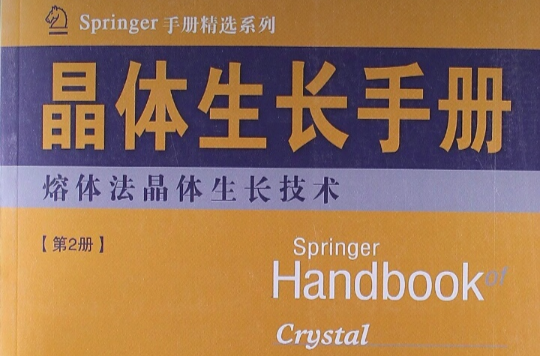
《晶體生長手冊2:熔體法晶體生長技術(影印版)》介紹體材料晶體的熔體生長,一種生長大尺寸晶體的關鍵方法。這一部分闡述了直拉單晶工藝、泡生法、布里茲曼法、浮區熔融等工藝,以及這些方法的最新進展,例如套用磁場的晶體生長、生長軸的取向、增加底基和形狀控制。
基本介紹
- 書名:晶體生長手冊2:熔體法晶體生長技術
- 作者:德哈納拉 (Govindhan Dhanaraj) 等
- 原版名稱:Springer Handbook of Crystal Growth
- ISBN:9787560338675
- 類別:晶體學
- 頁數:354
- 定價:76.00
- 出版社:哈爾濱工業大學出版社
- 出版時間:2013年1月1日
- 開本:16
- 語種:簡體中文, 英語
基本介紹
內容簡介
作者簡介
圖書目錄
PartB 熔體生長晶體技術
7.磷化銦:用穩定的磁場生長晶體及缺陷控制
7.1 歷史綜述
7.2 磁場下液體封蓋生長法
7.3 熔體的磁場接觸面
7.4 位錯密度
7.5 磁流量對雜質隔離的影響
7.6 InP:Fe的光學特徵
7.7 總結
參考文獻
8.半導體直拉矽單晶和太陽能電池套用
8.1 雷射掃描光散射技術生長矽單晶和太陽能電池套用
8.2 直拉矽單晶的晶體缺陷的控制
8.3 太陽能電池套用的多晶矽的生長和特徵
8.4 總結
參考文獻
9.氧化物光折變單晶的直拉生長法
9.1 背景
9.2 晶體生長
9.3 直拉生長系統的設計和發展
9.4 鈮酸鋰晶體的生長及其特性
9.5 其他氧化物光折變晶體
9.6 軟鉍礦晶體的生長及其特性
9.7 結論
參考文獻
10.三元化合物Ⅲ—V族半導體體材料晶體生長
10.1 Ⅲ—V族三元化合物半導體
10.2 三元化合物襯底的需求
10.3 器件級三元化合物襯底標準
10.4 布里茲曼晶體生長技術介紹
10.5 Ⅲ—V族的二元化合物晶體生長技術綜述
10.6 三元化合物相平衡
10.7 三元化合物半導體合金偏析
10.8 三元化合物晶體裂紋的形成
10.9 單晶三元化合物籽晶生產工藝
10.10 均質合金生長的溶質配備過程
10.11 熔體—固體界面形狀的作用
10.12 結論
參考文獻
11.用於紅外線探測器的銻基窄禁帶Ⅲ—V族半導體晶體的生長與特性
11.1 銻基半導體的重要性
11.2 相圖
11.3 晶體結構和成鍵
11.4 材料合成和提純
11.5 體材料InSb的生長
11.6 InSb、InAsxSb1-x.InBixSb1-x的結構特性
11.7 InSb、InAsxSb1-x.InBixSb1-x的物理性質
11.8 套用
11.9 結語與展望
參考文獻
12.光學浮區技術用於氧化物晶體生長
12.1 歷史
12.2 光學浮區技術——氧化物的套用
12.3 光學浮區及溶區移動晶體生長技術
12.4 浮區技術的優勢和局限
12.5 光學浮區爐
12.6 OFZT的陶瓷和晶棒生長的實驗細節
12.7 同成分和不同成分熔融氧化物的穩定生長
12.8 結構過冷和結晶前的穩定性
12.9 晶體生長的終止和冷卻
12.10 0FZ技術的晶體生長特點
12.11 晶體缺陷測定——實驗方法
12.12 0FZ和TSFZ方法選定氧化物單晶生長的具體條件
……
13.雷射加熱基座生長氧化物纖維
14.採用殼融技術合成高熔點材料
15.雷射基質氟化物和氧化物品體生長
16.晶體生長的成型
參考文獻
文摘
插圖:
(a) Single crystal wafers of 2 in (50 mm) or larger diameter must be available. Most commercial epitaxialgrowfh and device fabrication equipment is gearedtowards handling wafers of 50 mm or larger. Hencethe growth and fabrication conditions for any specific device structure need to be optimized usingthe geometries that will ultimately be used in largescale production.
(b) The spatial compositional inhomogeneity acrossthe entire wafer should be minimal (less than0.5 mol %). Variations in composition will lead todifferences in final device characteristics fabricatedacross the wafer.
(c) Wafers should be completely free from cracks,metallic inclusions, and multiphase regions. Theseare commonly observed defects in ternary crystalsand hence a great deal of care is necessary to avoidthem during growth.
(d) The dislocation density should be similar to that inexisting high-quality commercial binary substrates(less than 1000cm-2). Since the dislocations inthe substrate propagate into the epilayers, lowerdislocation density in the starting wafer is alwaysdesirable for better yield of reliable devices [ 10.1].
(e) A wide range of doping should be possible inthe substrate material in order to achieve desirable optical and electrical properties [10.32-38].For electronic devices, semi-insulating substratesare necessary. For infrared photodetector applications with back illumination (radiation incidentfrom the back of the substrate) or for light-emittingdiodes, the substrate must be optically transparentfor wavelengths that are being detected or emittedin the epilayers. The electrical resistivity or optical transparency can be altered by suitable impuritydoping of the bulk crystal. Even if lattice matching is achieved using a certain substrate material,if they do not have the necessary electrical or optical characteristics, the substrates are of little use forend applications. For example.

